Clamping Bushes MSA, boreholes 19 - 50 mm
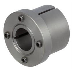
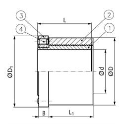
Material: Steel. Mechanical, all-steel clamping elements, containing no hydraulic pressure medium. Both inner part (1) and outer part (2) have a cylindrical buttress thread with a lengthwise slot. The inner ring (3) connected to the inner part (4) has threaded studs, that create a tensioning effect when tightened.The bushes are designed for very high loads in radial as well as in axial direction. The axial runout does usually not exceed 0,02 mm. If a clamping bush without slot on the outside part is to be welded onto a workpiece, we would ask you to contact us first. Feather key grooves in the shaft do not cause any problems; simply remove the frictional corrosion. Tolerance: Shaft h11 up to k6, Hub H7 up to H11 The values for the maximum transmittable torque and the maximum permissible axial force for the clamping bush at static load are stated in the table above. With dynamic load these values have to be reduced, i.e. divided by the operating factors listed in the adjoining table. Operating factor: See PDF-catalog page. 1) approximate surface pressure between clamping bush and hub.
Do you have a clamping set with a foreign designation?
Recode it here in our exchange Tool
| SKU | d [mm] | D [mm] | D1 [mm] | L [mm] | L1 [mm] | B [mm] | Transmissible Torque T [Nm] | Admissible Axial Load Pax [k N] | Surface Pressure [N/mm²] | No. of Pins [pcs] | Thread [mm] | Min. Torque M t [Nm] | Weight [kg] |
|---|---|---|---|---|---|---|---|---|---|---|---|---|---|
| 61501900 | 19 | 42 | 49 | 36 | 27 | 9,5 | 170 | 18 | 42 | 4 | M 6 x 12 | 8 | 0,33 |
| 61502000 | 20 | 42 | 49 | 36 | 27 | 9,5 | 180 | 18 | 42 | 4 | M 6 x 12 | 8 | 0,32 |
| 61502200 | 22 | 42 | 49 | 36 | 27 | 9,5 | 200 | 18 | 42 | 4 | M 6 x 12 | 8 | 0,31 |
| 61502400 | 24 | 46 | 53 | 37 | 27 | 10,5 | 325 | 27 | 58 | 6 | M 6 x 12 | 8 | 0,37 |
| 61502500 | 25 | 46 | 53 | 37 | 27 | 10,5 | 340 | 27 | 58 | 6 | M 6 x 12 | 8 | 0,36 |
| 61502800 | 28 | 55 | 63 | 44 | 32 | 12,5 | 490 | 35 | 66 | 4 | M 8 x 16 | 18 | 0,64 |
| 61503000 | 30 | 55 | 63 | 44 | 32 | 12,5 | 525 | 35 | 66 | 4 | M 8 x 16 | 18 | 0,61 |
| 61503200 | 32 | 60 | 67 | 49 | 37 | 12,5 | 650 | 41 | 60 | 5 | M 8 x 16 | 18 | 0,81 |
| 61503500 | 35 | 60 | 67 | 49 | 37 | 12,5 | 720 | 41 | 61 | 5 | M 8 x 16 | 18 | 0,75 |
| 61503800 | 38 | 67 | 75 | 57 | 45 | 12,5 | 950 | 50 | 54 | 6 | M 8 x 16 | 18 | 1,13 |
| 61504000 | 40 | 67 | 75 | 57 | 45 | 12,5 | 1000 | 50 | 54 | 6 | M 8 x 16 | 18 | 1,06 |
| 61504200 | 42 | 67 | 75 | 57 | 45 | 12,5 | 1050 | 50 | 54 | 6 | M 8 x 16 | 18 | 1,01 |
| 61504500 | 45 | 70 | 77 | 63 | 50 | 13,5 | 1280 | 57 | 53 | 7 | M 8 x 16 | 18 | 1,17 |
| 61504800 | 48 | 77 | 83 | 68,8 | 55 | 14,0 | 1560 | 65 | 50 | 8 | M 8 x 16 | 18 | 1,62 |
| 61505000 | 50 | 77 | 83 | 68,5 | 55 | 14,0 | 1625 | 65 | 50 | 8 | M 8 x 16 | 18 | 1,53 |